1 Version Record
| Version | Date | Description |
|---|---|---|
| 1.0 | 2026/4/30 | Initial Version |
2 Overview
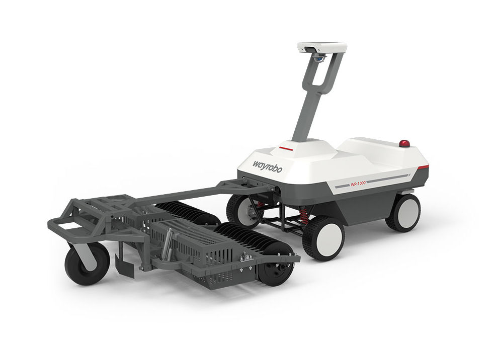
This document is used to guide agents through the entire process of golf ball picking robots from arrival, installation, positioning and configuration, mapping to trial operation and delivery. This document does not repeat the daily usage instructions for users, but only retains the steps, standards and precautions that must be mastered for on-site deployment.
The main deployment process is:
| Phase | Main Action | Completion Criteria |
|---|---|---|
| Preparation Before Deployment | Confirm the site, network, power supply, tools, differential account and materials | Material accounts are complete, and the installation point has construction and power supply conditions. |
| Robot unpacking and installation | Unpacking inspection, column reset, ball pickup mechanism installation, App binding | The equipment can be powered on, controlled remotely, and has no structural looseness. |
| Base Station Installation | Base station site selection, fixing, wiring, powering on, and registration | The base station is powered on stably and the satellite/differential status is normal. |
| Differential correction configuration | Choose the UHF/4G/NTRIP solution to complete the differential correction configuration and access of the robot | The robot has no "not connected to differential" faults |
| Construction of charging area and unloading area | Set up charging area and ball unloading platform | The power supply is safe, and the ball unloading path and platform meet the operating space |
| Software version update | Update robot firmware and mobile app | The version is the version required for delivery and the update is completed normally. |
| Mapping | Draw boundaries, return points, offloading points, restricted areas, hot zones, etc. | The map was saved successfully and the route planning was successful. |
| Robot trial operation acceptance | Test start, ball picking, ball unloading, return, obstacle avoidance, low battery return | The core process can be closed loop and customers can take over and use it. |
| Customer training | Training App, remote control, button, charging, daily inspection and abnormal reporting function applications | Customers can independently complete daily operations and basic inspections |
3 Preparation Before Deployment
3.1 Information and Accounts
| Item | Requirement |
|---|---|
| App account | Prepare a customer account or deliver a demo account, confirm that you can log in |
| Network information | Confirm the SIM card activation status, on-site 4G/Wi-Fi is available; confirm that the robot meets the server area requirements |
| Differential account | Prepare special information such as differential server IP, port, mount point, account number (not necessary) |
3.2 Site Conditions
| Check items | Requirement |
|---|---|
| work area | The terrain is relatively flat, with the slope in the working area not exceeding 20° and the slope in the boundary area not exceeding 15°. |
| Mapping period | Prioritize times when no one is playing or walking around, such as early in the morning or after closing. |
| Base station location | Open to the sky, with no obstruction within an altitude angle of 15°, close to the main work area |
| Charging area | Have reliable grounding power supply, rainproof, sunproof and moisture-proof measures and emergency power-off device |
| Offloading area | The ground is solid, the space is sufficient, and the air is open, which does not affect the operation of the stadium. |
| safe isolation | During mapping and remote control, no people, animals or mobile devices are allowed in the work area |
4 Robot Unpacking and Installation
4.1 Unpacking and Inspection
After unpacking, check the packing list and check whether the appearance, structural parts, cables and fasteners are missing or damaged. If you find deformation, damage, missing installation, or abnormal cables, you should take photos for documentation first, and then contact the project leader or after-sales support to confirm the handling method.
| Operation | Description | Image |
|---|---|---|
| Check A/B box materials | Check the delivery list item by item, focusing on the remote control, charger, base station, ball pickup mechanism, unloading table components and tool kits | |
| Check the body status | Confirm that the emergency stop bounces up, the tires are normal, the display screen can be turned on, and the brake lever is in the correct position. |
4.2 Body Installation
Before installation, make sure the robot is powered off and parked on a solid, level ground.
| Steps | Key Operation Points | Image |
|---|---|---|
| 1 | Straighten the column from the transport state to the upright state | |
| 2 | Use the vehicle-mounted M6 hexagon socket screws with flat spring washer to lock the column, and then use the M6 lock nut to reinforce it. | Same as above |
| 3 | Install the front and rear covers of the column and confirm that all screws are tightened |
Note: When tightening the screws, tighten them gradually in diagonal order to avoid uneven stress on the sliding teeth or structure caused by over-tightening at a single point.
4.3 Ball Pickup Mechanism Installation
| Steps | Key Operation Points | Image |
|---|---|---|
| 1 | Use pins and cotter pins to install the pickup drum and bracket onto the universal wheel bracket. | |
| 2 | Install the push rod to the fuselage connection position using the pin and cotter pin | |
| 3 | Connect the push rod motor cable and confirm that the interface is reliable and the cable is not pulled. | Need to add a picture: Close view of push rod motor cable connection |
Caution: The cotter pin must be bent to prevent it from falling off after being inserted to prevent the pin from loosening during operation and causing the mechanism to fall.
4.4 App Binding and Out-of-Box Setup
| Steps | Key Operation Points | Image |
|---|---|---|
| 1 | Scan the QR code with your mobile phone to install the App | |
| 2 | Log in to WayRobo App using your delivery account and follow the prompts to complete the agreement and permission authorization. | |
| 3 | Click "Add", scan the QR code on the robot display, turn on Bluetooth and search for the device to complete the binding. | Same as above |
| 4 | Put down the front baffle of the packaging box as a pallet, enter the App remote control interface, and the low-speed remote control robot slowly drives out |
Warning: The obstacle avoidance function does not take effect in remote control mode. When taking out the box and building a map for remote control, the operator needs to keep a safe distance of more than 5m and ensure that the driving path is free of people, animals and obstacles.
After unpacking, you need to install the various parts of the robot, which mainly include: - Body installation: Restore the robot's column position and tighten the screws and cover. - Installation of the ball-picking mechanism: Use the latch and cotter pin to install the ball-picking drum and bracket on the universal wheel bracket, connect the ball-picking mechanism and the body, and install the cable interface of the push rod motor.
5 Base Station Installation
5.1 Differential Correction Option Selection
| plan | Applicable scenarios | priority | Key conditions |
|---|---|---|---|
| Self-built base station UHF direct transmission | There is no obstruction between the base station and the robot, and the UHF signal can cover the work area, home point and ball unloading point. | priority | The frequency of the base station and the robot radio are consistent |
| Self-built base station 4G differential | UHF is obviously blocked or the radio station is not compliant, but both the base station and the robot can connect to the Internet stably. | alternative | The base station, robot and differential server are bound together |
| NTRIP account difference | Unable to use self-built base stations or reliable NTRIP services already available locally | alternative | Obtain the local service provider IP, port, mount point, username, and password |
5.2 Base Station Site Selection
| No. | Base station selection and installation requirements | Example |
|---|---|---|
| 1 | The base station is close to the robot working area and has stable power supply available; | |
| 2 | There is a hard ground or fixed wall for installing the base station, and there are no obstacles around it; | |
| 3 | There is no obstruction to the sky, and there is no obstruction within the height angle of 15° within the field of view of the base station installation position, so as to avoid obstruction by the ceilings of buildings and trees; | |
| 4 | UHF transmission is unobstructed. Avoid obstruction by metal, walls, trees, etc. between the base station and the robot operating area, especially near the ball unloading point; When 4G transmits differentially, it is enough to ensure that the base station has no obstruction to the air and the 4G signal at the installation location is good; |
|
| 5 | Stay away from sources of interference: More than 200m away from high-power wireless power sources such as TV stations, radio stations, microwave stations, and high-voltage wire towers; more than 50m away from high-voltage transmission lines and microwave transmission channels |
5.3 Base Station Installation
| No. | Base station installation steps | Example |
|---|---|---|
| 1 | 【Prepare fixed position】 For ground installation, open four holes on the planned fixed ground, and the hole positions must correspond to the base of the installation bracket. For vertical installation, open two holes on the wall where you plan to fix it. The hole positions must correspond to the sides of the mounting bracket. ⚠️Note:
|
|
| 2 | [Installation bracket] Embed the expansion screw, install the M10 flat washer and elastic washer and tighten |
|
| 3 | 【Install SIM card】 Insert the SIM card when the power is off |
|
| 4 | [Fixed base station body] For ground installation, align the screw holes at the bottom of the base station with the screws above the support pole, screw in and tighten. For vertical installation, align the bottom of the base station with the hole of the L-shaped mounting bracket, then install the screws from the bottom and tighten them. |
|
| 5 | [Connecting cables and antennas] Install the UHF antenna and power cord and confirm that the connection is reliable. The base station can automatically turn on after power is supplied. ⚠️Note: The power cord needs to be fixed on the bracket with a tie to prevent external force from pulling off the power cord and causing the interface to be disconnected. |
5.4 Base Station Indicator Status
| No. | Indicator lights (from left to right) | normal state |
|---|---|---|
| 1 | Recorder light | Always extinguished |
| 2 | satellite light | red light flashing |
| 3 | Differential lamp | Red light flashes 1HZ |
| 4 | power light | Green light is always on |
6 Differential correction configuration of base station and robot (Key point)
6.1 Base station management terminal login and registration
| No. | Steps | Example |
|---|---|---|
| 1 | Connect your computer or mobile phone to the base station WIFI hotspot: The WiFi name is the SN number of the base station. The SN number can be viewed on the nameplate of the fuselage. WiFi initial default password: 12345678 |
/ |
| 2 | After successfully connecting to the hotspot, use your computer or mobile phone to open the browser and enter192.168.1.1Enter the login page, enter your username and password and click Login Username: admin The password is: password |
|
| 3 | The normal login page is as shown in the figure | |
| 4 | After logging in to the management terminalClick“"Others - Device Registration", enter the registration code and click Submit. | |
| 5 | Obtain the file corresponding to the registration code of the base station SN code: Please contact our technical support to obtain regularly updated registration codes. ⚠️Notice:
|
6.2 Robot Positioning Differential Correction Configuration
The robot has three ways to obtain the difference: - Self-built base station, UHF radio direct transmission - Self-built base station, forwarded through differential server after 4G networking - If there is no self-built base station, configure the NTRIP account to connect the difference.
6.2.1 Self-built base station UHF direct transmission differential(preferred)
This section describes how to configure UHF differential mode. The core requirement is that the base station and robot radio frequencies are consistent. The detailed steps are as follows:
| No. | Steps | Example |
|---|---|---|
| 1 | [Working mode-base station] Log in to the base station management background, enter the receiver configuration-working mode page, and set the working mode to "base station" |
|
| 2 | [Startup mode-single point] Select Single Click for "Startup Mode" and click Save. ⚠️Notice: Setting a single point is so that the base station can independently obtain the initial position. This step is essential after the base station is newly installed or changed. |
|
| 3 | [Startup mode-fixed coordinates] Select fixed coordinates in "Startup Mode" and click "Get Current Coordinates".Click 5 to 10 times until there is no big change in longitude and latitude (there is no big fluctuation in the fifth decimal place of longitude and latitude); [Data link-built-in TRIMTALK radio]
|
|
| 4 | [Base station status check and confirmation]
⚠️Warning: Different models of GNSS antennas and UHF modules may have different parameters. If they need to be replaced, please modify the frequency settings simultaneously to avoid signal interference. |
|
| 5 | [Enter the robot’s local WEB]
In general, please select a different server through the cloud WEB, and click on the homepage to enter the corresponding robot management background. |
|
| 6 | [Ball picking machine UHF radio frequency configuration-WEB] The default frequency of the ball picking machine is 460.0125Mhz, and generally there is no need to configure it. Configuration method:
⚠️Tips: The fault can be re-detected through the App. If the "not connected to differential" fault has been eliminated, it means that the robot has been connected to differential normally. |
|
| 6 | [Ball picking machine UHF radio frequency configuration-App]
|
6.2.2 Self-built base station 4G differential (optional)
It is suitable for sites with obvious UHF obstruction, but both base stations and robots can be connected to the Internet stably. The specific configuration steps are as follows:
| No. | Base station configuration steps | Example |
|---|---|---|
| 1 | [WEB Cloud Create a new base station account]
|
|
[Base station management side I/O account configuration]
|
||
[Confirm base station 4G connection status]
⚠️Note: If the base station is still offline, you can try to power on and off the base station again after saving the configuration. |
| No. | Robot configuration steps | Example |
|---|---|---|
| 1 | [WEB Cloud Create a new rover account]
|
|
| 2 | 【Bind base station】
|
|
| 3 | [Enter the robot’s local WEB]
In general, please select a different server through the cloud WEB, and click on the homepage to enter the corresponding robot management background. |
|
| 4 | [Robot differential correction configuration-WEB]
⚠️Tips: The fault can be re-detected through the App. If the "not connected to differential" fault has been eliminated, it means that the robot has been connected to differential normally. |
|
| 5 | [Robot Differential Configuration-App]
|
6.2.3 NTRIP account difference (alternative plan)
If the local base station cannot be used normally, differential data can be obtained by configuring the robot with an NTRIP account provided by the local service provider. This configuration process requires remote connection to the robot terminal. The specific steps are as follows:
| No. | Steps | Example |
|---|---|---|
| 1 | 【Get NTRIP account】 Obtain an account through the local NTRIP service provider. The account information must include: IP address, port, source node, username, password ⚠️Note: The example account is for example only and cannot be used. |
|
| 2 | [Local WEB closes software differential correction configuration]
|
|
| 3 | [Enter the robot console]
|
|
| 4 | [Configure NTRIP account]
Note that you need to change the domain name to an IP address. For example, after obtaining the NTRIP account information, you can send the command: ⚠️Note: The example account is for example only and cannot be used. |
|
| 5 | [Important configuration-backloading GGA data to NTRIP server] After the NTRIP account configuration is completed, enter the following commands in order to return GPGGA information to the differential server. Restart the M2 module to save the configuration. After completion, the differential can be started normally. ⚠️Note: Different servers may have different configuration requirements. If the configuration fails, you need to contact the development team in time. |
|
| 6 | [Restart robot service]
⚠️Tips: The fault can be re-detected through the App. If the "not connected to differential" fault has been eliminated, it means that the robot has been connected to differential normally. |
7 Construction of charging area and unloading area
7.1 Charging area
| Item | Requirement |
|---|---|
| Location | Close to the main work area, with convenient transportation, avoiding densely populated areas and main stadium passages |
| power supply | Use a reliable grounded socket; the wire diameter is not less than 2.5mm²; supports 1300W and above power ⚠️Danger: It is prohibited to share power lines with other high-power equipment to prevent line overloading; |
| Protect | Must be equipped with leakage protector RCD, the maximum trip protection current is not less than 20A |
| protection | Be equipped with measures to prevent rain, sun and moisture, and give priority to a well-ventilated and sheltered location. |
| emergency | Equipped with emergency power-off device to quickly cut off the power supply in case of abnormality |
7.2 First time charging
| Steps | Operation |
|---|---|
| 1 | Park the robot smoothly and make sure the charging port is dry and free of foreign matter. |
| 2 | Connect the charger's three-pin plug to the 220V/110V AC power supply |
| 3 | Insert the charger output end into the robot charging port and lock it |
| 4 | After charging, unplug the charger and close the charging port protective cover tightly. |
Equipment that is new from the factory or has been stored for a long time should be fully charged before first use. If the device is used for the first time or has been powered off for more than 15 days, it is recommended to drain the battery to 0% and then charge it to 100% to calibrate the remaining battery display.
7.3 Offloading area
| Item | Requirement |
|---|---|
| Location | The terrain is flat, the space is sufficient, it does not affect the operation of the stadium, and it is easy for staff to enter. |
| ground | Solid, dry, and no obvious slope to prevent the robot from slipping or tilting |
| vision | Open air with no obvious obstruction ensures stable positioning |
| Safety | Warning signs are set up around the perimeter and no one is allowed to approach during the operation. |
| route | Reserve a straight alignment path before unloading the ball platform to avoid getting on the platform at a large angle |
During the ball picking operation, when the system detects that the ball basket is full, the equipment will automatically go to the ball unloading point, and the push rodis at the ball collecting frame of the ball picking mechanismThe motor rises and completes ball unloading. Combined with the ball unloading platform and conveyor system, manual intervention can be minimized and operating costs can be reduced. According to the operational needs of different golf courses, the following two ball unloading platform solutions can be used:
| plan | Applicable scenarios | Description | Image |
|---|---|---|---|
| Climbing simple ball unloading platform | Quick deployment and inconvenient construction sites | There is no need to dig a hole, it can be built directly on the existing ground; the balls enter the ball washing process through manual transfer or elevator. | |
| Sunken ball unloading platform | Sites that can be constructed and renovated to pursue higher automation | Holes need to be dug and drained; the balls enter the temporary storage and ball washing process through the elevator or ball flushing pipe. |
8 Software version update
8.1 Update robot firmware
In order to give full play to the performance of the robot, it is necessary to upgrade the latest firmware of the robot before official use. The update method is: 1. Turn on the robot and keep it connected to the 4G/Wi-Fi network; 2. Follow the App's prompts and wait 10–15 minutes for the update process; 3. Do not operate the machine or shut it down during the process. You can only use it after the App prompts "update successful".
⚠️Note:
Before updating firmware please make sure: - The robot is connected to the Internet and the signal is good and stable; - Robot battery power exceeds 20%; - There are no work tasks for the next hour.
8.2 Update App
In order to give full play to the performance of the robot, please upgrade to the latest App before official use, as follows: - Enter the mobile app store to update - Enter App-My-About Us-Check for Updates - Scan the QR code to update
9 Set the workspace(Key point)
⚠️Note: - Before mapping, all self-test conditions must be passed; - When building a map, keep the status of the robot and mobile phone normal, and the mobile app is in the foreground; - After building the map, the robot will automatically plan seven working paths in different directions within the map range. The mission can be started after the first path planning is completed, and the remaining six will be planned silently in the background during idle time or during the mission.
9.1 draw borders
9.1.1 Drawing Boundary Steps
| No. | Drawing Boundary Steps | Example |
|---|---|---|
| 1 | After your phone is connected to the robot, click "Create Map". At this time, the robot will perform a self-test to ensure that the robot is fault-free and in an idle state. After passing the self-test, click "Next" to enter the map drawing interface. |
|
| 2 | Use the remote control, or enter the remote control in the App to control,Remote control the robot to any suitable point on the boundary of the work area as the starting point for drawing the boundary. | |
| 3 | Click "Start" on the App, go around the boundary and "mark points" along the path to form a closed route. Return to the starting point and click "Finish". At this time, the current stop point will be connected to the starting point to form a closed area, and the boundary of the work area is drawn. | |
| 5 | ⚠️Notice:
|
9.1.2 Drawing boundary requirements
| No. | Drawing boundary requirements | Example |
|---|---|---|
| 1 | The working area needs to include the entire stadium, and the left side of the robot can be controlled to draw close to the stadium guardrail. | |
| 2 | If there is a restricted area that spans the entire stadium and the robot cannot completely plan it, it is recommended to draw the work area. | |
| 3 | The boundaries of the working areas cannot intersect when constructing a map using points. | |
| 4 | The mapping area of the working area must not be less than 20mx20m in length and width, otherwise the route planning will fail. | |
| 5 | Draw the boundary and try to control the left limit of the robot close to the edge of the court. ⚠️Note: Failure to stay close to the boundary will result in a large area on the side where the ball cannot be picked up. |
9.2 Create a home point
9.2.1 Steps to create a home point
| No. | Steps to create a home point | Example |
|---|---|---|
| 1 | After creating the work area, you will automatically enter the home point creation, or manually click "Home Point", carefully read the pop-up drawing prompts, click "Start", start from the work area, and the remote control robot will pass to the return point. | |
| 2 | After the remote control robot moves along the channel route to the home point, click "Finish" to save the home point and return channel. | |
| 3 | ⚠️Notice:
|
9.2.2 Create a return point request
| No. | Create a return point request | Example |
|---|---|---|
| 1 | The actual width of the return channel is 5 meters. When drawing, ensure that there are no fixed obstacles and dangerous areas within the range to prevent the robot from stopping when it returns to avoid obstacles. | |
| 2 | When establishing a charging path, try to make as small a turn as possible. If the curve is too sharp, it will be difficult for the robot to track and may easily lead to tracking failure. | |
| 3 | When establishing a charging path, avoid repeated intersections between the channel and the work area, which may cause the ball pickup machine to not return along the preset path. | |
| 4 |
|
|
| 5 |
|
9.3 Create a release point
9.3.1 Steps to create a release point
| No. | Steps to create a release point | Example |
|---|---|---|
| 1 | Click "Unloading Point", carefully read the pop-up drawing prompts, click "Start", and start from the work area to draw a channel leading to the unloading point. | |
| 2 | After starting the drawing, the remote control robot travels along the channel route to the ball unloading point. The ball unloading point should ensure that the ball outlet of the ball basket is facing the ball unloading port of the ball unloading platform. Click "Finish" to save the unloading point and unloading channel. | |
| 3 | ⚠️Notice:
|
9.3.2 Create discharge point requirements
| No. | Create discharge point requirements | Example |
|---|---|---|
| 1 |
|
|
| 2 | When establishing the ball unloading point, try to ensure that the ball is unloaded in a straight line along the center line of the ball unloading table. Do not make adjustments at large angles. Try to ensure that the final parking position is in the middle of the ball unloading table to improve the success rate of ball unloading. | |
| 3 |
|
|
| 4 |
⚠️Notice: When the equipment climbs the unloading table, there is a safety risk because it does not recognize obstacles; if the surrounding unnecessary obstacles are not shielded, obstacle avoidance will be triggered. |
|
| 5 | Do not set the left and right sides of the unloading table and the back of the unloading table as return points, work areas or passage areas. | |
| 6 | The ball unloading path and the charging path should not intersect outside the channel area. After intersecting, there will be the possibility of crossing paths due to channel interoperability, which may lead to abnormality in the area where the robot is located. Treatment measures:
|
|
| 7 | ⚠️Note:
|
9.4 Draw restricted areas
9.4.1 Steps to draw restricted areas
| No. | Steps to create a restricted area | Example |
|---|---|---|
| 1 | When the following areas exist in the workspace, they need to be set as restricted areas:
|
|
| 2 | Choose different drawing methods according to the area and shape of the restricted area. For larger areas (such as sand pits, ponds, etc.), it is recommended to use the boundary line method; for smaller obstacles (such as code signs, net bags, flagpoles, etc.), it is recommended to use the photo frame method. | |
| 3 | Boundary Surrounding: Click "Add"->"Restricted Area"->"Boundary Surrounding" in sequence. After carefully reading the pop-up prompts, control the robot to drive to the starting point of the edge of the restricted area, and then click "Start" on the App.Go around the border and "mark points" along the pathCreate a closed pattern on the app that includes obstacles, return to near the starting point, click "Save" to completeThe addition of this obstacle area。 | |
| 4 | Photo frame selection: Click "Add" → "Restricted Area" → "Photo frame selection". Control the device to drive near the obstacle and click "Start". The system will automatically capture the image and drag the rectangular frame on the image to select the obstacle area. If the position is not accurate, you can click "Retake" to reselect the frame. After clicking "OK", the data will be automatically uploaded; after confirming the coverage, click "Save" to complete the addition of the restricted area. ⚠️Note:
|
|
| 5 | ⚠️Warning: All areas in the work area that should be set as restricted areas must be set as restricted areas to avoid affecting the normal operation of the robot, or even damaging the robot or property and endangering personal safety. |
9.4.2 Restricted area location requirements
| No. | Restricted area location requirements | Example |
|---|---|---|
| 1 | Do not cross the entire work area in restricted areas (including temporary restricted areas), otherwise the robot planning will fail. | |
| 2 | The restricted area (including temporary restricted area) cannot completely surround the blank work area, otherwise the path planning will fail. If necessary, the entire area can be set as a restricted area. | |
| 3 | Do not set the restricted area on the ball unloading path or charging path, otherwise the robot may not be able to return to the home point and ball unloading point. | |
| 4 | Do not set the restricted area within 5 meters of the starting point of the ball unloading path or the starting point of the charging path, otherwise the robot may not be able to return to the home point and ball unloading point normally. | |
| 5 | Slopes greater than 20° are set as restricted areas to prevent the robot from failing to climb, frequent overcurrent in the driving wheels, and path tracking failure. | |
| 6 | In order to improve the efficiency of picking up the ball and ensure safety, the temporary penalty area should be located on one side of the court as much as possible and intersect with the boundary of the work area. Otherwise, the robot's efficiency in picking up the ball will be affected, and problems may occur when it is too close to the boundary. |
9.4.3 Photo frame selection to establish restricted area requirements
| No. | Photo frame selection to establish restricted area requirements | Example |
|---|---|---|
| 1 | If the object in the restricted area is large in size and the front and side lengths are similar, it is necessary to take photos and mark them from two facades, establish the restricted area twice for the same object, and splice each other to cover the entire restricted area. | |
| 2 | After selecting the target and clicking to identify it, please do not move or adjust the target frame until the restricted area is saved. | |
| 3 | The target frame cannot simply frame the target. It needs to be adjusted in size appropriately and follow the principle: the foreground proportion of the target in the frame is greater than the background area.
|
9.5 Create temporary exclusion zones (optional)
Temporary restricted area: Robots are not allowed to enter the temporary restricted area after it is turned on to ensure the safety of the site. It can be crossed normally when it is not turned on.
Under normal circumstances, the area around the teeing table is set up as a temporary restricted area. When no one is playing at night, it is then opened for robots to enter and pick up balls.
9.5.1 Steps to create time zone restricted areas
| No. | Steps to create time zone restricted areas | Example |
|---|---|---|
| 1 | Move the robot to the starting point of the restricted area, click "Add"->"Restricted Period"->"Start", and then remotely control the robotMake a circuit around the boundary of the restricted area during the time period and "mark points" along the pathCreate a closed pattern on the app, return to the starting point, click "Finish" to saveAddition of restricted areas during this period。 |
9.5.2 Create time zone restricted requirements
Refer to 8.4.2 and 8.4.3 to create restricted area requirements.
9.6 Draw hot zones (optional)
Not mandatory, but creating a hot zone can improve ball picking efficiency. After creation, you can set priority for picking up hot spots and customize the frequency of picking up balls in hot spots.
9.6.1 Steps to Draw Hot Zones
| No. | Steps to Draw Hot Zones | Example |
|---|---|---|
| 1 | Enter the "Map Edit" interface and click "Add"->"Hot Zone"->"Start". | |
| 2 | Drag the map so that the center cursor is located on the boundary of the hot area to be drawn. Each time you click "Plot", a marker point will be drawn. If you want to delete the latest marked point, you can click the "Undo" button; if you want to restore the undone mark point, please click the "Redo" button. | |
| 3 | After all the marker points are drawn, click "Finish", and the system will connect the marker points two by two according to the order of drawing to form a closed area. Click "Save"->"Confirm" to save the enclosed area as a hot zone. | |
| 4 | ⚠️Notice:
|
9.6.2 Create hot zone requirements
| No. | Requirements for mapping hot zones | Example |
|---|---|---|
| 1 | Priority is given to setting up hot zones in areas with dense ball volume. The hot zone range fits multiple areas of the ball, reducing the range of ineffective non-hot zones and improving ball picking efficiency. | |
| 2 | The length and width of hot zone mapping must be greater than 20m×20m, otherwise the hot zone path planning will fail. | |
| 3 | Most areas in the hot zone need to be kept at least 8m away from the boundary of the field, otherwise the planned path will be too small, affecting the efficiency of picking up the ball. | |
| 4 | Avoid setting areas that are severely concave, convex, or close to B-shape, otherwise it will easily cause path planning failure or path deformation, affecting the efficiency of picking up the ball. |
9.7 save map
When the map boundaries, return point, unloading point, restricted area (optional), time restricted area (optional), and hot zone (optional) are all set, click "Save" to save the map. Subsequently, the robot background will automatically plan the path to pick up the ball in the current map. The time required for planning changes due to changes in factors such as the size of the work area and the settings of the restricted area, but is usually within 1 minute.
9.8 View and edit maps
You can view the entire saved map on the App's map interface, and on the "My Stadium" interface, you can edit, modify, delete, and copy the map.
Edit map: In the "My Stadium" interface, click "Edit Map". The robot will start self-checking. After meeting the mapping conditions, it will enter the map editing interface. In this interface, click on the created boundary, return point, unloading point, restricted area or period restricted area, and hot zone to complete the selection and deletion. You can also add these elements again. The method is the same as when creating the map.
9.9 Draw access zones (optional)
After completing and saving the drawing of the ball unloading point, you can draw a passage area for adjusting the body posture of the robot when it goes to the ball unloading table and returns to the work area.When the site conditions permit, follow the prompts to draw an area on the ball unloading channel to facilitate the robot to enter the ball unloading point along multiple routes and avoid using fixed routes that cause repeated crushing of the lawn.
9.9.1 Drawing access zone requirements
| No. | Draw channel area requirements | Example |
|---|---|---|
| 1 | The access area must include all accessible areas around the unloading table, and all surrounding obstacles must be excluded from the access area. | |
| 2 | The access area must be connected to the bottom of the ball unloading table, and a safety gap of more than 0.5 meters should be reserved between the bottom of the ball unloading table. | |
| 3 | The width of the narrowest part of the passage area must be greater than 3m; Sections less than 3m need to cut off the passage area, and then proceed along the preset unloading path. |
|
| 4 |
|
9.10 Draw the turnaround area (optional)
9.10.1 Drawing turnaround area requirements
| No. | Drawing turnaround area requirements | Example |
|---|---|---|
| 1 | The turnaround area must be set in the passage area or work area, with priority being set in the passage area. | |
| 2 | It is recommended that the U-turn area be set to a size of 6m×6m. The larger the area, the higher the efficiency of turning around and returning to the work area; under the size of 6m×6m, the equipment only needs one reversal to complete each U-turn. | |
| 3 | Sufficient space needs to be reserved horizontally in the U-turn area. It is recommended that in addition to the U-turn area itself, a distance of more than 5m should be reserved horizontally on one side of the passage area/work area; If the site conditions cannot reserve 5m, priority can be given to appropriately reducing the size of the U-turn area. |
|
| 4 | At least a 0.5m safety distance should be reserved between the U-turn area and the boundaries of the work area and passage area to ensure safe equipment operation. | |
| 5 | When it is necessary to turn right and make a U-turn, set the U-turn area on the left side of the passage area/work area; When it is necessary to turn left and make a U-turn, set the U-turn area on the right side of the passage area/work area. |
10 Trial operation and acceptance
10.1 On-site inspection after map construction
| Check items | standard |
|---|---|
| position | The robot position on the App map is consistent with the on-site position. The positioning icon is green and the positioning solution is fixed. |
| map elements | Boundaries, return points, unloading points, penalty areas, hot zones, etc. are displayed correctly |
| path planning | After saving, the path planning is successful and there is no planning failure prompt. |
| Return channel | There are no obstacles, no stagnant water, and no narrow/sharp bends in the passage. |
| Unloading channel | There are no obstacles within 2.5m on both sides of the ball unloading path, and the straight alignment area in front of the platform meets the requirements. |
| restricted area coverage | All sand pits, ponds, flagpoles, signboards, dangerous slopes, etc. are covered |
| base station signal | The work area, return point, and ball unloading point can all maintain stable differential and positioning |
10.2 Functional test run
| test | Operation | pass standard |
|---|---|---|
| Remote control test | App/remote control forward, backward, and turn at low speed | Response is normal, no abnormal alarms |
| automatic start | Place the robot in a non-restricted area in the work area and click Start | Can enter the automatic ball picking task |
| Avoid restricted areas | Observe the path performance of the robot when it approaches the restricted area | Do not enter restricted areas |
| Manual ball unloading | App click "Unload Ball" | Can reach the ball unloading point along the ball unloading channel and complete the ball unloading action |
| Automatic return | App click "Return" or return after the mission is over | You can return to the home point along the return channel |
| emergency stop | Press emergency stop under safe conditions | If the driver is powered off, the robot will stop immediately; it can be restored after being released. |
| Exception prompt | Manually trigger controllable minor anomalies or view the alarm page, such as parking the robot under the eaves to create positioning anomalies. | App/display prompts are clear and can be retested and restored. |
10.3 Delivery acceptance criteria
A complete closed loop should be completed at least once before delivery: start the task -> execute the ball picking path -> return to the ball unloading point -> complete the ball unloading -> return to the work area or home point. If on-site time is limited, the two key tests of "manual ball unloading" and "manual return to home" should also be completed.
| Acceptance results | Processing method |
|---|---|
| All passed | Enter customer training and delivery sign-off |
| Unstable positioning | Prioritize checking for base station obstruction, UHF/4G differential, SIM/network and electromagnetic interference |
| Unloading failed | Prioritize adjustment of the ball unloading point, ball unloading platform alignment, straight line area in front of the platform and obstacle shielding range |
| Planning failed | Check boundary intersections, no-go zone crossings, hot zone dimensions, and empty areas surrounded by no-go zones |
| Return failed | Check the return channel width, sharp turns, obstacles, and intersection relationship with the work area/ball unloading channel |
10.4 Delivery record
| Item | Record |
|---|---|
| Client/Court Name | |
| Robot SN | |
| Base station SN | |
| Differential mode | UHF / 4G / NTRIP |
| Base station installation location | |
| Trial run conclusion | Passed / pending correction |
| Matters to be rectified | |
| Customer Training Confirmor |
11 Commonly used function tutorials
11.1 Base station offset calibration function
This section mainly introduces the method to avoid redrawing the map when the robot needs to move or replace the base station after building the map.
In practical applications, the three most likely situations are as follows: 1. The base station changes the fixed position(distance less than 300m) 2. The fixed position remains unchanged and the base station is replaced. 3. The fixed position changes and the base station is replaced at the same time
The following describes the operation steps according to different scenarios:
11.1.1 Base station changes fixed position
When it's time to move the base station to a new location, follow these steps:
| No. | Steps | Example |
|---|---|---|
| 1 | [Preparation before calibration]
You can observe the positioning status icon through: WEB, App, and display screen |
|
| 2 | [Turn on the base station offset calibration switch] The base station calibration switch can be turned on through the App developer mode/local WEB:
|
web side: App side: |
| 3 | [Mobile base station location] Just do it manually(distance less than 300m) |
|
| 4 | 【Base station status confirmation】
|
|
| [Click to get the offset] Click on App/local web to get the offset |
||
[Configure offset coordinates into the base station]
Note: Sometimes there is a problem with decimal point input in the background of the base station. It may be necessary to input all the numbers before adding a decimal point. |
||
| 7 | 【Offset accuracy confirmation】
|
|
| 8 | [Close calibration switch] The display accuracy is up to standard. You need to manually click to turn off the calibration switch. |
11.1.2 The fixed position remains unchanged and the base station is replaced.
The fixed position remains unchanged. When replacing a new base station, you only need to record the base station coordinates of the old base station and then configure it into the new base station.
For specific operations, you need to log in to the old base station management terminal - record the three data of longitude, latitude and height - log in to the new base station management terminal - write and save the configuration.
11.1.3 Fixed location change, base station replacement
When you need to use a new base station and the new base station is not at the same location as the old base station, please follow the steps below:
| No. | Steps | Example |
|---|---|---|
| 1 | [Preparation before calibration]
You can observe the positioning status icon through: WEB, App, and display screen |
|
| 2 | [Turn on the base station offset calibration switch] The base station calibration switch can be turned on through the App developer mode/local WEB:
|
web side: App side: |
| 3 | [Turn off the old base station and turn on the new base station]
|
|
| 4 | [Click to get the offset] Click on App/local web to get the offset |
|
| 5 | [Configure offset coordinates into the base station]
Note: Sometimes there is a problem with decimal point input in the background of the base station. It may be necessary to input all the numbers before adding a decimal point. |
|
| 6 | 【Offset accuracy confirmation】
|
|
| 7 | [Close calibration switch] The display accuracy is up to standard. You need to manually click to turn off the calibration switch. |
|
| [Close calibration switch] The display accuracy is up to standard. You need to manually click to turn off the calibration switch. |
11.2 Switch device server
App - My - Developer mode - Switch device server - Select robot and server - Click "Save" to complete the switch
12 4G Router Setup Guide
12.1 Router Configuration Objectives
- 4G network connection is operational.
- Robot controller (domain control) can communicate within the local network.
- Router broadcasts a Wi-Fi hotspot.
12.1.1 IP Address Allocation Plan
| Device | IP Address |
|---|---|
| Router LAN IP | 172.31.31.1 |
| Robot Controller | 172.31.31.3 |
| Positioning Module | 172.31.31.101 |
| LiDAR | 172.31.31.201 |
| Wi-Fi Debugging Devices | 172.31.31.220 ~ 172.31.31.239 |
12.2 Preparation Before Configuration
12.2.1 Required Items
| Item | Purpose |
|---|---|
| USR-G806s Router (with power supply) | Device to be configured |
| 4G SIM Card | Internet access |
| Robot Antenna | Receives 4G signal |
| PC | Access router web management page |
| Ethernet Cable | Connect PC to router LAN port |
12.2.2 Installation Steps (Power Off)
Complete the following before powering on the router: 1. Insert the SIM card. 2. Tighten the 4G antenna. 3. Tighten the Wi-Fi antenna. 4. Connect the PC to a LAN port using an Ethernet cable. 5. Power on the router.
Note: Do not connect the computer to the WAN port. During configuration, always use a LAN port.
12.3 Computer Network Settings
It is recommended to configure the computer with a static IP address.
12.3.1 Windows Configuration Path
Control Panel
→ Network and Internet
→ Ethernet
→ Edit IP settings
→ Enable IPv4
→ Select Manual IP configuration
IP Address: 192.168.1.2
Subnet Mask: 255.255.255.0
Save changes.
12.4 Log In to Router Management Interface
Open a browser and enter:
192.168.1.1
Default credentials:
Username: root
Password: root
After logging in, you will enter the router management page.
Note: After changing the LAN IP, the login address will become:
172.31.31.1
12.5 Detailed 4G Router Configuration Steps
| Step Name | Operation Instruction | Photo |
|---|---|---|
| Set 4G as the Preferred Internet Connection | Navigate to Network → Network Switch → Select 4G Priority → Save | |
| Configure 4G Keep-Alive Detection | 1. Network → APN Settings → Keep-alive Configuration → Check Enable Custom probe address 1: 112.74.61.22Probe address 2: 8.8.8.8Ping retry count: 4 → Save & Apply 2. Go to Info page and record SIM ICCID |
|
| Configure Ethernet Ports as LAN Ports | Port Mode → Mode Selection → Set WAN/LAN = LAN → Save | |
| Change Router LAN IP Address | Network → Interfaces → Edit LAN interface IPv4 Address: 172.31.31.1 / Subnet Mask:255.255.255.0 Custom DNS: 8.8.8.8 , 114.114.114.114 → Save |
|
| Configure DHCP Address Pool | Leave DHCP disabled (unchecked). Start IP:220, Client Quantity:20 → Save This allocates IP addresses to temporary devices such as phones and laptops: |
|
| Save Interface Configuration | After saving, web access switches to 172.31.31.1; browser disconnection is normal. Wait approximately 30 seconds and reconnect. | |
| Configure Router Wi-Fi | Network → Wireless → Basic Settings Configure: SSID:Default name Mode:Access Point (AP) → Save Wireless Security: Encryption Mode:WPA2-PSK, default Wi-Fi password:88888888 → Save |
|
| Enable Wi-Fi RF | Network → Wireless → Advanced Settings → Check Enable RF Switch → Save | |
| Sync System Time | System → System → Basic Settings → Select the time zone corresponding to the robot deployment location. → Save & Apply Important: The router time zone must match the robot's configured time zone. |
|
| Scheduled Daily Reboot | System → Scheduled Reboot Under Parameter Configuration:
Click Save & Apply. |
|
| Save full config & Reboot | System → Reboot → Click Reboot Wait for the router to restart. |
12.6 Router One-Click Configuration Import
12.6.1 Preparation
Confirm the following are available:
Router configuration backup file
Generate from:System → Backup/Upgrade → Download Backup → Generate Backup
Ethernet cable
Brand-new router
Laptop
Important
Do NOT encrypt the configuration backup file.
12.6.2 Configuration Import Procedure
Step 1
Set the computer Ethernet adapter to:
192.168.1.x
Connect the computer directly to the router and log in at:
192.168.1.1
Step 2
Navigate to:
System → Backup/Upgrade
Select:
Upload Backup and Restore Configuration
Choose the backup file and click:
Upload Backup
Step 3
Change the computer Ethernet adapter IP to:
172.31.31.x
Open:
172.31.31.1
Verify that the router management interface is accessible.
Step 4
If the router time zone needs adjustment, it is recommended to export backup files for commonly used time zones.
Note: In the configuration import video, the import procedure begins at approximately the 3-minute mark.
12.7 APN Configuration Reference
Before configuring the APN, obtain the following information from your mobile carrier, IoT SIM provider, traffic card supplier, or private network service provider.
| Item | Description | Example |
|---|---|---|
| APN Name | Most important parameter; specifies which mobile data network to connect to | cmnet, iot, enterprise APN |
| Username | Required by some APNs; may be blank | user001 or blank |
| Password | Required by some APNs; may be blank | password001 or blank |
| Authentication Type | PAP / CHAP / PAP or CHAP / None | PAP, CHAP, None |
| Dial Number | Commonly used by 4G routers | *99# |
| PDP Type / IP Type | IPv4 / IPv6 / IPv4v6 | IPv4 or IPv4v6 |
Recommendation: Confirm all APN parameters with the SIM card provider before configuration to ensure successful network registration.
If you have any further questions during use, or if the interface has changed and the information in this guide no longer matches the actual product, please contact our technical support team for guidance and assistance. We will be happy to support you!